Vanguard65 Build Guide
Before you begin
Upon receiving your keyboard, please carefully inspect the unit for any damage during transit. While we tried our hardest to prevent any damage, you may never know! If you notice any damage to the unit itself, please contact us and we’ll sort it out.
Download Files
- Keymap (JSON): Download
Optional Files
- Firmware (HEX): Download
What you'll need
- Precision screw driver set
- Keyboard keycap set
- Keyboard stabilizers
- Keyboard mechanical switches
What's in the box
- 1 Keyboard case
- 1 Brass weight
- 1 Hotswap PCB
- 1 plate
- Case and plate foam
- 4 Case feet
- 12 Gasket socks
- 8 Case screws
- 1 Knob screw
- 1 Slider screw
- 2 diffusers
- 4 daughter board screws
- 1 Aluminum knob
- 1 Aluminum slider handle
- 1 Daughter board
- 1 JST cable
Decide on the layout
Before inserting switches to the PCB, decide on the layout that you would like to have configured. Note, you can always change this at a later time, hence the luxury of a hotswap keyboard.

Build Steps
Setup Hotswap PCB
#1 Install Stabilizers
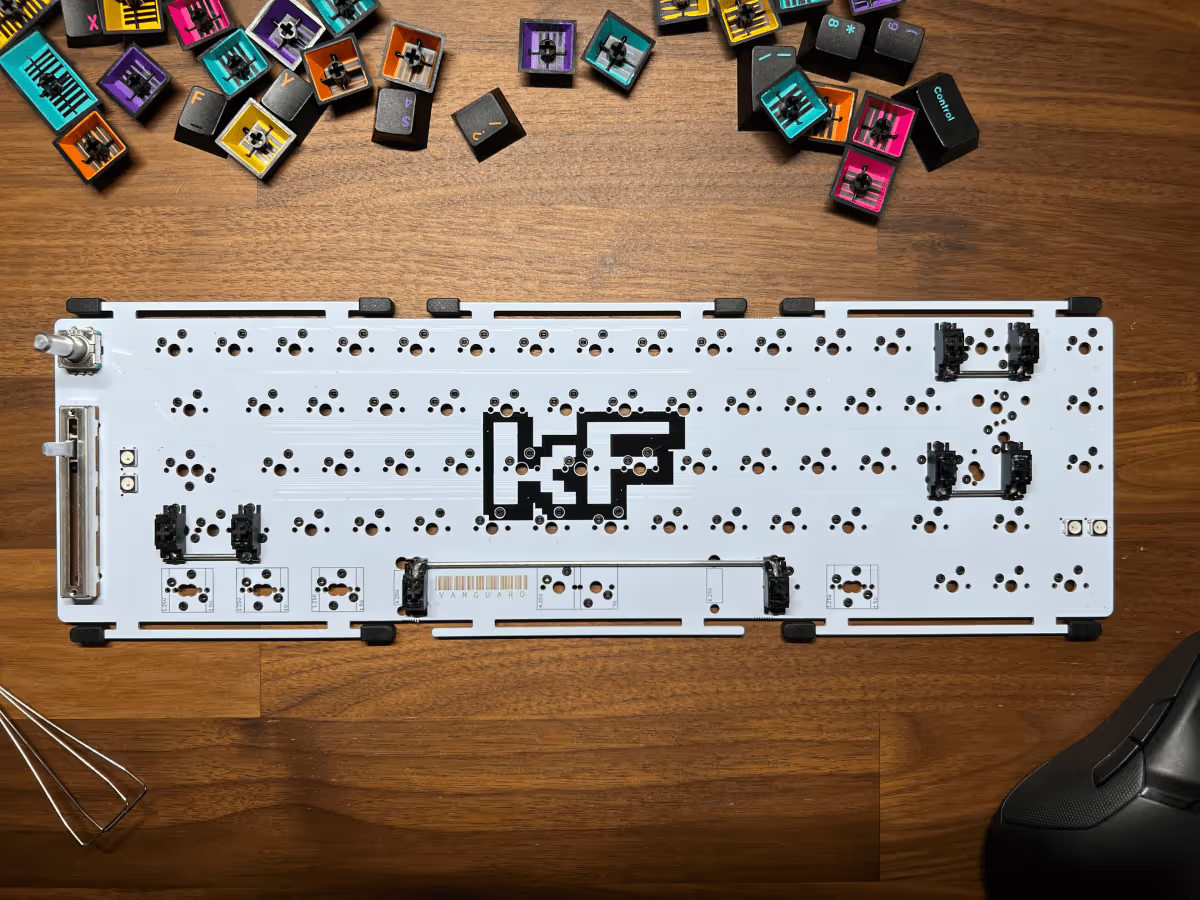
Depending on your decided layout, this may vary slightly.
#2 Install Gasket Socks

#3 Add Plate Foam (optional)
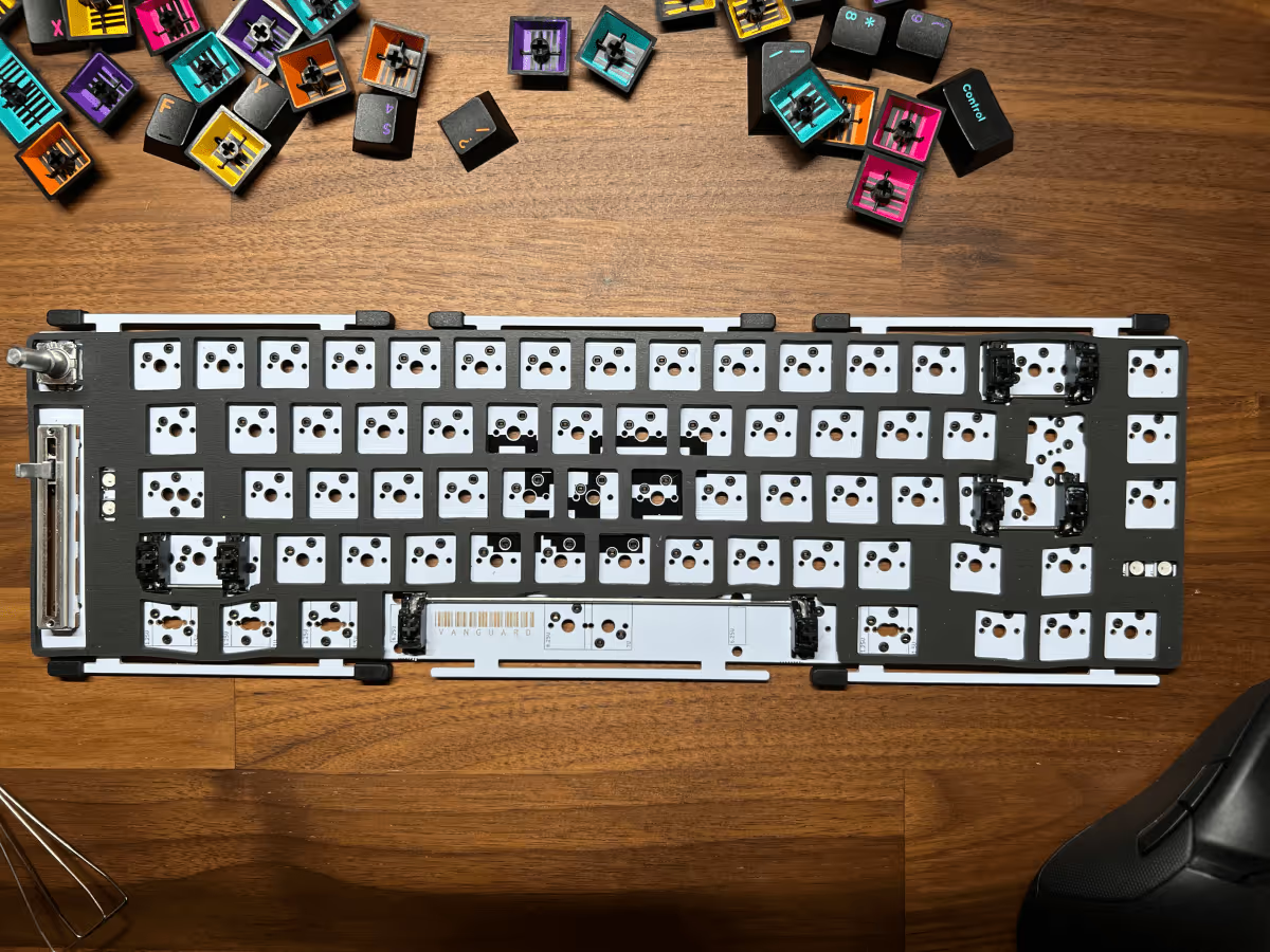
If you do not wish to add your foam then you can skip this part. You can always add it later.
#4 Install Switches (with plate)
Warning
Once you've ensured that the legs of the switch are straight, insert it through the switch plate and into the hotswap socket on the PCB. While doing so, make sure the bottom of the socket is supported by your thumb so the socket does not accidentally get pushed out of place. Also, make sure the switch is fully seated and is level with the top of the switch plate.

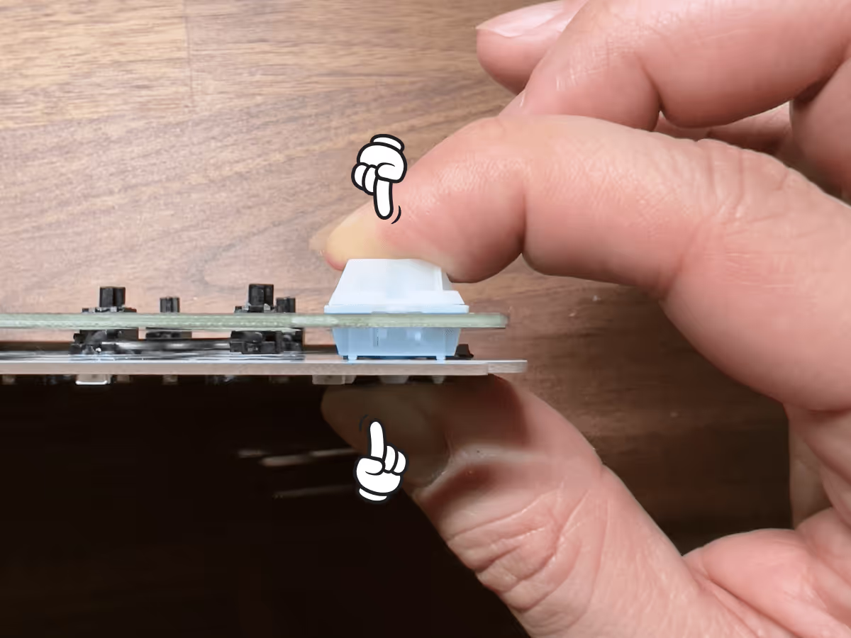
If you find that you need to apply too much force, recheck that the switch pins are straight. After you've installed the first few switches successfully, insert the ones for the thumb area in to make sure they'll fit in properly. As before, make sure you are supporting the the bottom of the socket while pressing the switches in.
Prefer to go plateless?
#5 Add Keycaps
Once you have completed the steps for setting up your Hotswap PCB, we can start the assembly of the keyboard case.
Setup the keyboard case
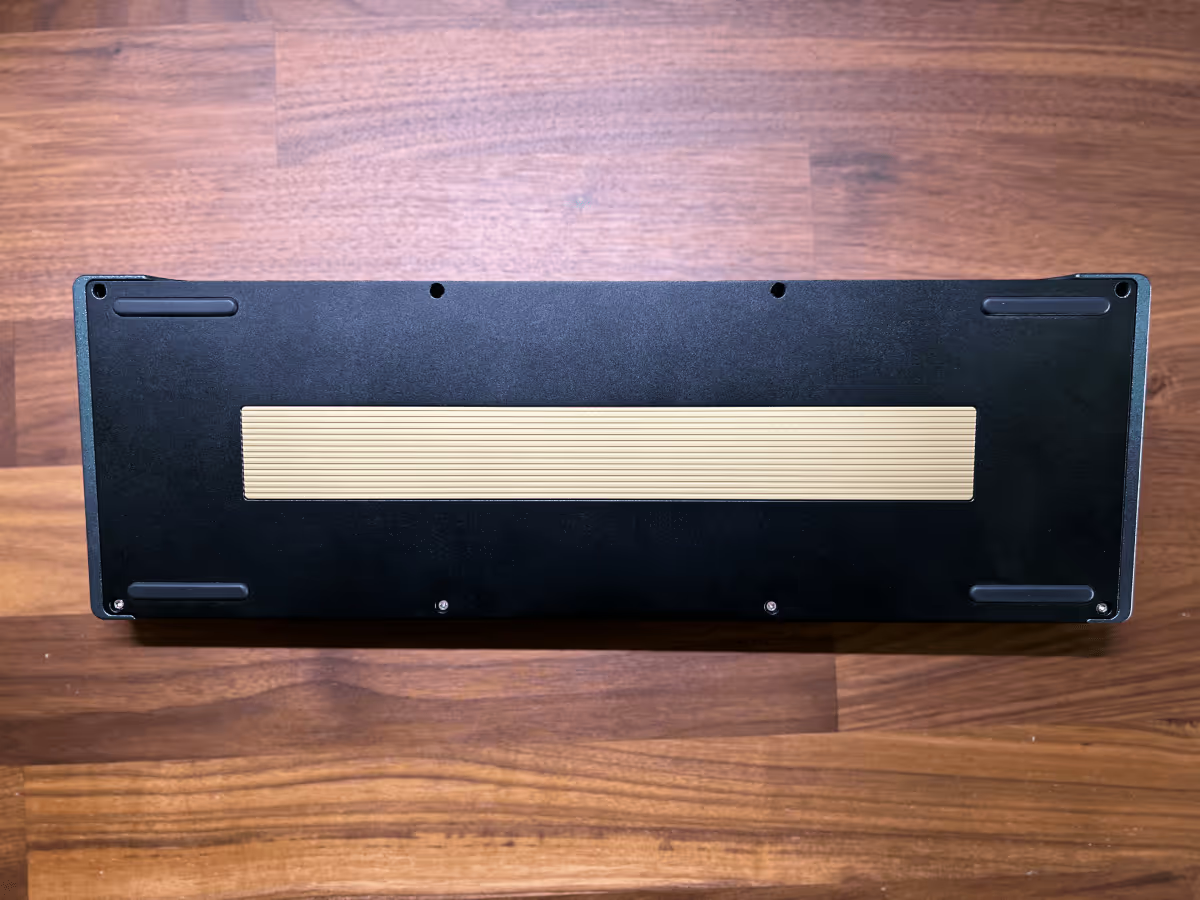
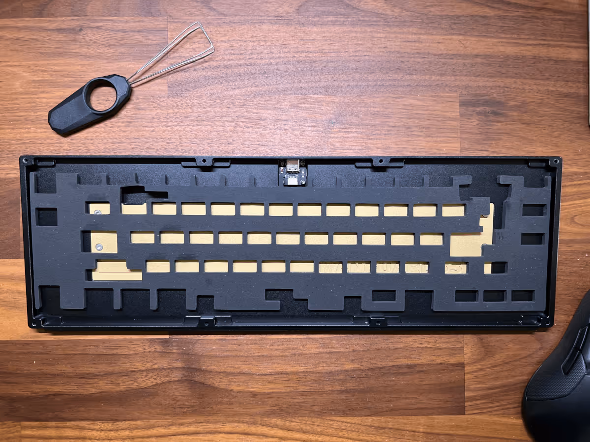
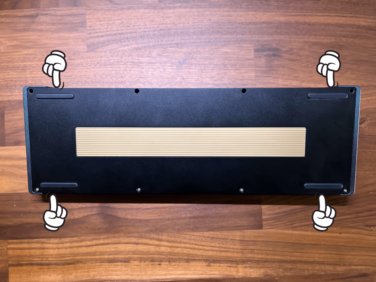
#6 Disassemble case
The first thing that you'll need to do is unscrew the bottom frame. Flip your board over and unscrew the 8 screws.
#7 Install daughter board
Unscrew the 4 daughter board screws from the bottom case.

Place daughter board, align the holes, and re-fasten the 4 screws.

Install the JST cable and connect to the PCB.
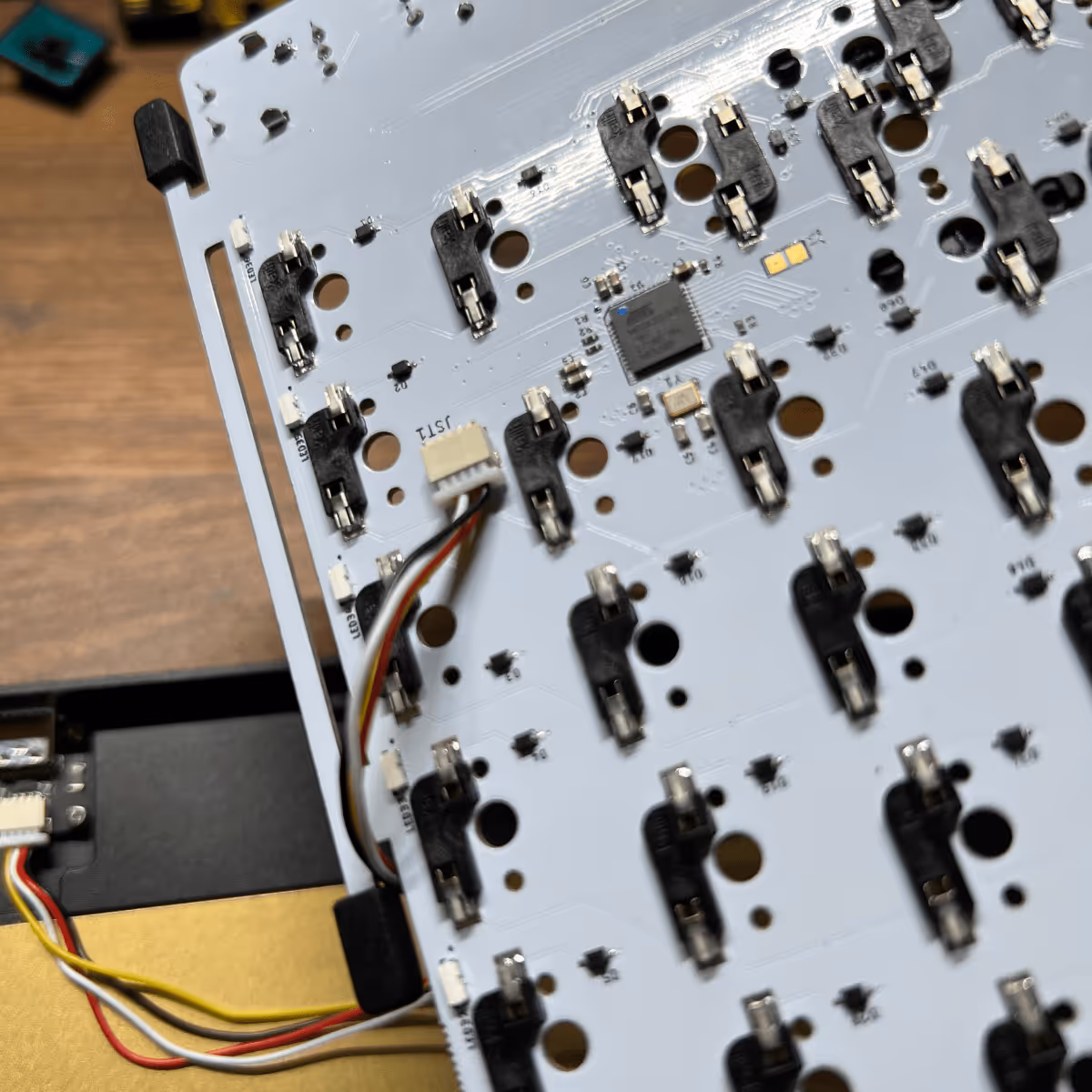
Warning
#8 Add case foam (optional)
If you do not wish to add your foam then you can skip this part. You can always add it later.
#9 Install PCB
Gently align and place the PCB on top of the bottom case.
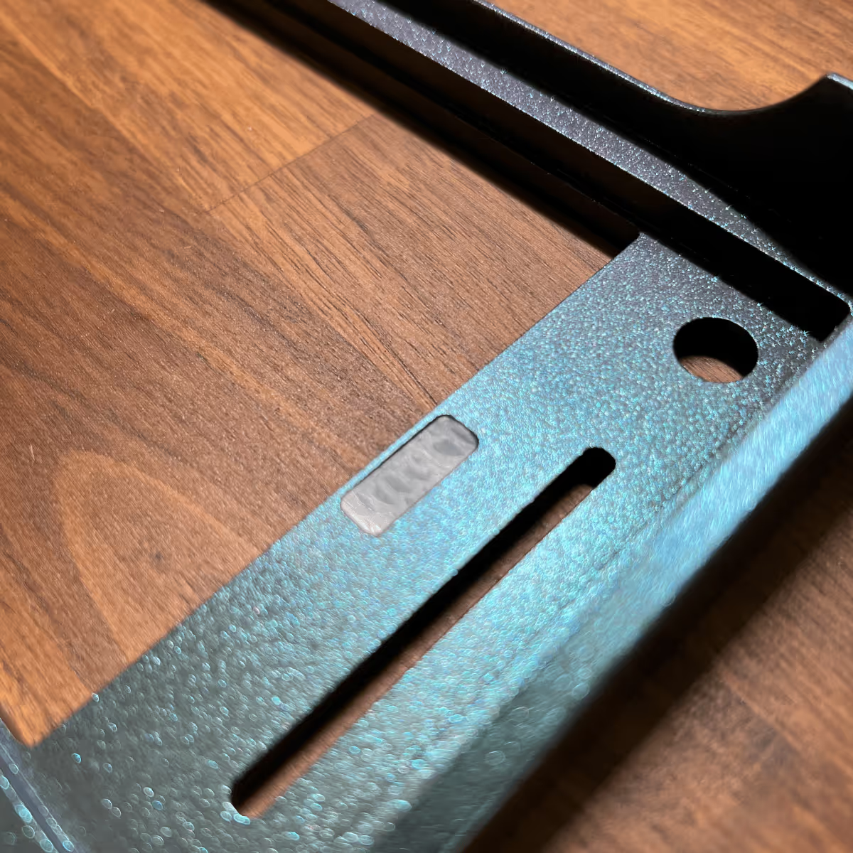
#10 Install diffusers
Add the 2 diffusers to the cutouts located underneath the top case. There is an insert located on each side.
Note
#11 Install top case
Take the top frame and place on top to close the keyboard case. Flip your board over and fasten the 8 case screws in order to lock everything in place.
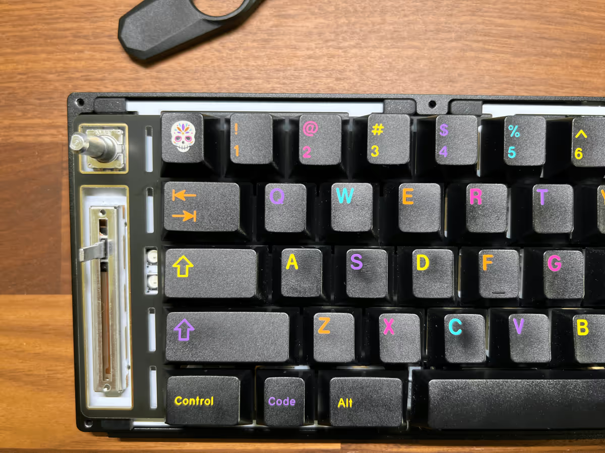
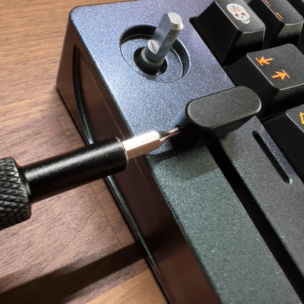
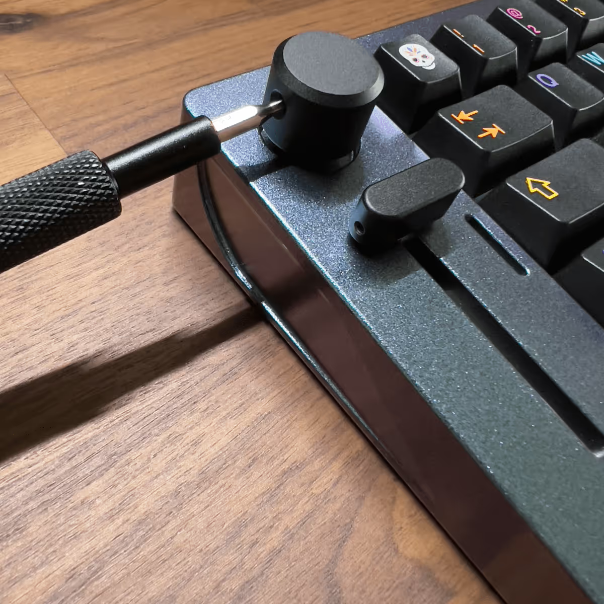
#12 Install knob & slider
Flip your keyboard back to normal position and install both the knob and slider handle using your screw driver.
Note
#13 Install case feet
Peel adhesive side from the case feet and install to the 4 areas located at the bottom case. And you're done!
Configure Layout using VIA
Before you can use VIA to configure your keyboard layout, you must perform the following steps to have it all setup:
- Open VIA
- Click the Settings (Cog icon)
- Enable "Show Design Tab"
- Click the Design tab (paint brush icon)
- Click the Load draft definition
- Upload the JSON file.
Slider Functions

We built a VIA extension that allows users to easily adjust the function of the slider.
Using MIDI mode
When in MIDI mode, the slider can be compatible with the following apps after setting up some plugins.
Here is a listing of suggested plugins to check out:
- MIDI Mixer: Has plugins for Discord, Spotify, OBS, Philips Hue, Wave XLR, Home Assistant, Twitch, and more.
- Adobe Lightroom Classic Integration (MIDI2LR)
- BetterTouchTool
- MIDI Translator Pro
- REAPER
- More 3rd party apps will be listed soon, check back frequently.
Using Layer Switch mode
Switch between your assigned keymap layers.
- 0-25%: Layer 0
- 26-50%: Layer 1
- 51-75%: Layer 2
- 76-100%: Layer 3
Using RGB Brightness Control
Set the brightness levels of the case underglow.